Xiamen, China · Global OEM Manufacturing Support[email protected]
Home / Technology / Process selection guide
Engineering buyer guide · updated October 8, 2026

CNC milling vs turning—and when 3-axis or 5-axis matters.

The best machining route follows the part geometry, critical datums, quantity and inspection plan. This guide helps OEM buyers describe the requirement before requesting a drawing-based quote from METIC and Hongye.

Quick process comparison

QuestionCNC millingCNC turning
Primary geometryPrismatic faces, pockets, slots and non-round contoursRotational features such as shafts, sleeves, bushings and bores
Main motionRotating cutter removes material from a held workpieceRotating workpiece is cut by a tool
Typical added operationsDrilling, tapping, finishing or EDM for inaccessible featuresDrilling, threading, milling flats or slots on a turn-mill route
Check before quotingAccess to every face, setup count, fixture datums and thin wallsConcentricity, long/slender geometry, cross-holes and secondary features

Many parts need both processes. The drawing and planned sequence—not a marketing label—determine the route.

When is 3-axis milling enough?

For accessible top-facing pockets, holes and profiles, 3-axis milling may be a simpler choice. Features on other faces can still be machined by re-fixturing the part. The key question is whether those setups preserve the required relationships between critical surfaces.

When should 5-axis be reviewed?

Features on multiple angled faces, compound surfaces or restricted tool access may benefit from 5-axis machining. Fewer setups can help datum control, but do not automatically make every feature more accurate or every job cheaper. Machine travel, tool reach, fixture access, programming and inspection must all be reviewed for the actual CAD model.
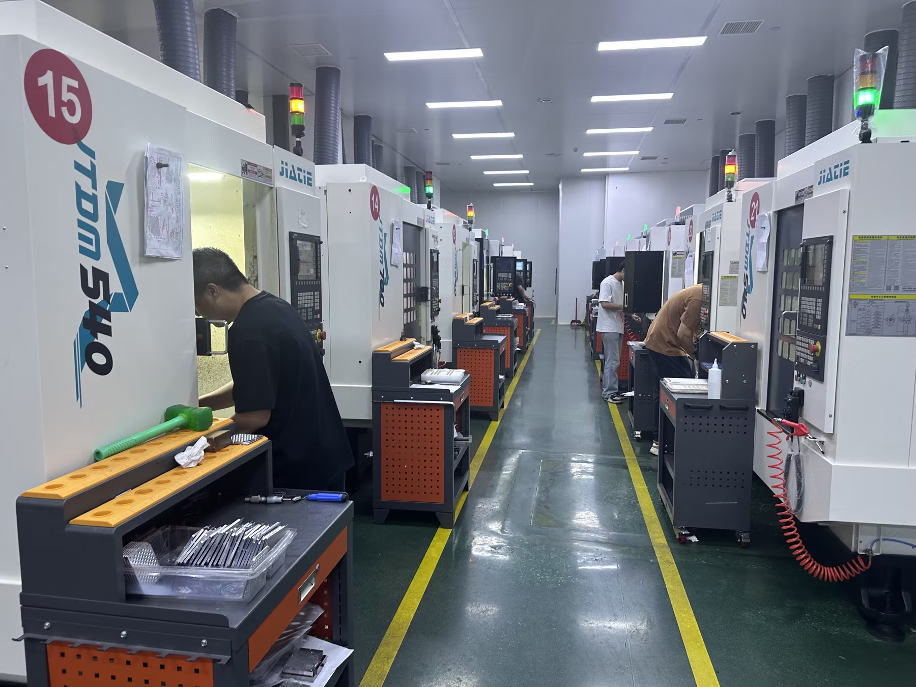
Rows of CNC machining centers in Hongye's Xiamen workshop
Hongye CNC production area
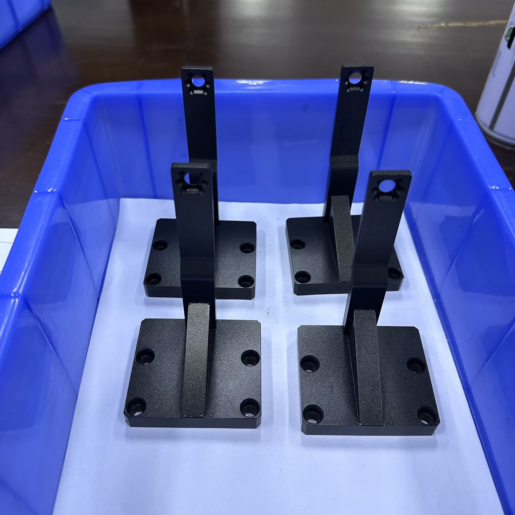
Actual machined brackets showing base holes and upright connection features
Multi-face bracket example
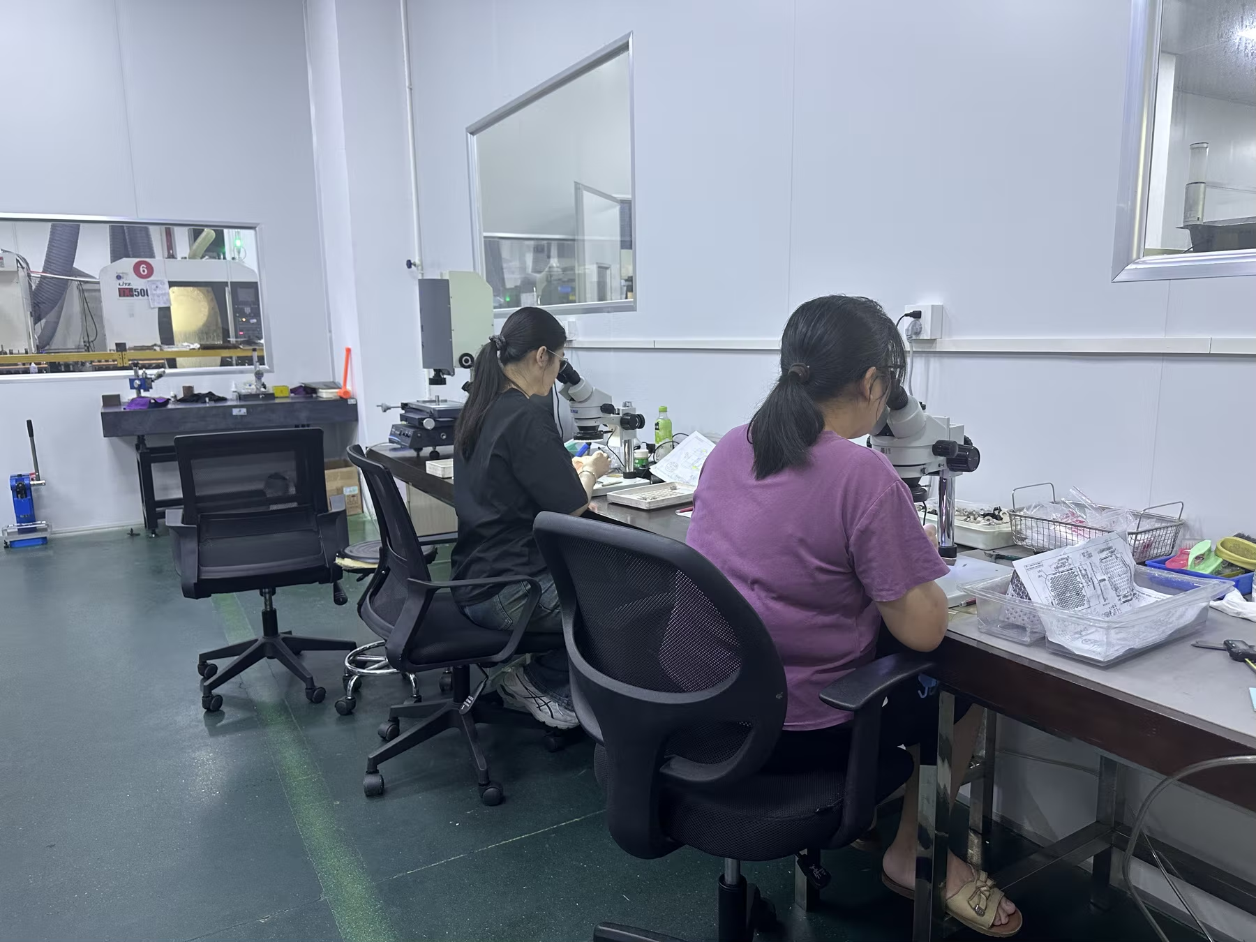
Inspection staff using optical equipment for small components
Inspection area

Factory and component photographs are real examples, not proof that a specific photographed part used a particular axis configuration or achieved an unstated tolerance.

Examples of route selection

Mounting bracket: Flat base, upright arms and connection holes suggest milling and hole-making. Feature position and perpendicularity may matter more than the visible surface finish. The actual drawing determines whether multiple 3-axis setups or a multi-axis approach is preferable.

Turned cylindrical component: A shaft, sleeve or round end-piece generally begins with turning. Flats, cross-holes or off-axis slots may call for secondary milling or a turn-mill setup. Specify concentricity and datum requirements rather than assuming one machine can verify them all.

Mold plate: Repeated cavities and holes call for a tooling route that may combine milling with EDM, wire cutting or finishing. Cavity consistency and tool access should be assessed against the mold design.

Do not choose the process from tolerance alone

Material, geometry, setup, temperature, finishing and the measurement method all affect an achievable result. Mark the functionally critical dimensions and datum references on the drawing. Agree first-article or sample inspection, CMM suitability and report format during quotation.

METIC coordinates international enquiries and project communication. Hongye is the associated manufacturing team in Xiamen. This article is process-selection guidance, not a guarantee that every listed machine or tolerance is suitable for every part.

Unsure which route fits your part?

Send the drawing. We will review the manufacturing and inspection scope before quoting.

Request a Quote →
WA